All posts by Sheetal Rajput

Cavity Diplexers and Their Importance

Cavity diplexers are three port devices used in Tranceivers (transmitter and receiver) to separate the Transmitter frequency band from the receiver frequency band. They share a common antenna while working simultaneously at different frequencies. A diplexer is basically a high and a low pass filter connected to an antenna.

The transmitter part of the diplexer is different from the receiver in function its function is to filter out the transmitter sidebands that are generated ensuring the transmitter radiates within its allotted spectrum band and does not spill into adjacent frequency allocations. The receiver part of the diplexer is to protect the receiver from the overload on the transmitter. Diplexers are used on all duplex tranceivers covering all bands from high frequency to milliwave.

For example in a  wireless communication system. The diplexer is to receive the passband of 1710 MHz to 1785 MHz and a to transmit the passband of 1805 MHz to 1880 MHz. Providing the unusual passband and notch responses for the overcrowded mobile sites.

Applications: One of the applications of the diplexer is to connect the dual band mobile radio’s two antenna connection to a common feed line.

Raditek makes cavity diplexers from 30MHz to 60GHz in power ranges from milliwatts to kilowatts

Waveguide Components: Importance and Application

A waveguide is a guided medium to transmit electromagnetic energy from one place to another. They usually operate in dominant mode. Also, they have cut off frequency, unlike two-wire transmission line. They support various modes.

Some of the components of waveguide are:

  • • Load – This is responsible for absorbing microwave energy from the system
  • • Tuner – This component is used to match the load impedance with the source impedance.
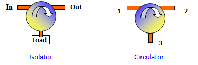
  • • Isolator – They are circulators which have three ports and are responsible for transmitting microwave energy between the different ports while directing and reflecting energy to a port with an attached load.
  • • Power Measuring (couplers)– These are the devices made to couple power taken from the waveguide system which helps in measuring power, frequency, and other parameters to ensure proper flow of energy.

Importance of Waveguide Components:

  • • They are guided so there is no chance of leakage of energy.
  • • They can handle high power.
  • • They provide wide bandwidth.
  • • They are strong in structure and durable as well.
  • • They ensure the least amount of loss in a high-frequency application. Such as mm-wave application.
  • • Inherently behaves as a high pass filter and many more.

Application of Waveguide Components:

  • • Simply as a transmission line
  • • A waveguide is also used to make various passive components like a filter, divider horn antennas, etc.
  • • It can be used to measure and regulate high power.
  • • It can also work at very high frequencies.

Waveguides have a crucial role to play in any microwave. Therefore, it becomes essential to check and select the waveguide that offers optimum performance and abides by safety standards.

Raditek waveguide components can be seen at https://raditek.com/Waveguide-Components.html

The Linearity of a Microwave Amplifier

What does Linearity of an RF/Microwave amplifier mean?

It is one of the essential jobs of the amplifier. It is used to increase the power level of the input signal without having to alter the content of the incoming signal. This term ‘linearity’ is derived from the linear relationship between the input and output power. In an ideal amplifier, this would be related to the gain made by the amplifier.

However, it is not as easy as it sounds. It involves matching complex matching circuits to facilitate the flow from a low impedance of solid state to a higher impedance. But still, most amplifiers will have to suffer again roll off at the higher frequencies inevitably. In order to get high amplifier linearity, you will have to sacrifice on efficiency.

What deprives an amplifier of its linearity?

Amplifiers are not the ideal devices to have transfer characteristics, because they can generate harmonic signals multiple times the fundamental input signal. The intermodulation distortion also gets amplified along with it.

Non-linearity can also occur due to time. These non-linarites occur due to memory effects. It can happen when an input signal stresses the power supply voltage which results in creating input signal dependent non-linarites which are also known as the memory effects.

If anyone wants to extend transistor life and maintain good linearity, it is crucial to have thermal management for the microwave amplifier. It is because the linearity is dependent upon the temperature as cold or hot transistors exhibit different functions.

Raditek microwave amplifiers can be seen at http://raditek.com/AMPLIFIERS/Microwave-Amplifiers.htm

A Brief Insight of Coaxial Couplers

The RF Directional Coupler is an instrument for measuring or monitoring microwave power consisting of a line section which is inserted in any of the RF-lines. It could be coaxial lines, waveguides, tri-plate lines, wirelines, etc. The line is inserted between a transmitter or generator or amplifier and its load. It allows sampling of microwave energy without moving parts and adjusting. It is a simple and convenient means to do so.

Raditek Directional couplers are used for various applications that involve measurement, power monitoring, etc. A directional coupler can be used for isolating, eliminating or combining signals in microwave signal routing and RF. Coupled, Input, Transmitted and Isolated – are the four ports in a directional coupler.

The distinguishing features of directional couplers can be listed as coupling, insertion loss, mainline and auxiliary line, directivity, power handling capability, bandwidth, frequency sensitivity, etc. There are various types of directional couplers which have different sampling capabilities like coaxial directional coupler, dual directional coupler, Hybrid couplers, Bethe-hole coupler, Multi-hole coupler, etc.

Coaxial Coupler

One of the various types of the directional coupler is a Coaxial Coupler. They are usually used at frequencies ranging from 10 MHz to 40 GHz. They are commonly designed for low Voltage Standing Wave Ratio (VSWR) and insertion loss, high directivity, and flat coupling level.

They are suitable for 49GB systems, and some of its applications include general purpose test and measurement systems. There are two designs in the coaxial directional coupler – single-ended and dual directional.

The design of a single-ended coaxial directional coupler has the general appearance of a section of the coaxial line, with a second parallel section of line with one terminated end. The dual-directional coaxial coupler consists of two single-ended directional couplers connected back-to-back. They are used to allow measurement of forward and reflected power levels.

Applications

There is a varied range of applications for directional couplers. It is used as power sampler in measurement systems. It is commonly used for measuring and monitoring microwave power. It is also used for measuring and monitoring of frequency in operating systems.

One can guarantee constant conditions for physical, thermal or chemical process in the load as another application of the directional coupler is to use the signal of the forward wave for the regulation system to keep forward power constant. Directional reflectors can also be used for making use of isolation. In case isolation is high, they combine signals to feed a single line to a receiver.

Raditek couplers can be seen at https://raditek.com/smt-quadhybrid.htm

Power Splitter – Resistive, Reaction, and Wilkinson

Power splitter, also widely known as Power Divider, is a device that divides a radio frequency microwave input signal into any number of output signals and while doing so, it maintains the characteristic impedance of the input. They are widely used in labs, radar and communication systems and test instrumentation etc. They are categorized broadly into two- Resistive and Reactive.

Resistive Power Splitter

The characteristics of the resistive power splitters make it perfectly suitable for a few appliances and not so ideal for some. The units are generally smaller as they are made of lumped elements. They are extremely broadband, and it is the only type that operates DC onwards. Their power handling capacity is low. For applications where insertion loss and isolation are important factors, Resistive Power Splitters aren’t suitable because they have high loss and poor isolation. They are widely chosen for their simplicity as well. They are simple and can be made easily in a circuit and require minimal design and preparation. If the right resistors are used, and the construction is done right, the frequency response will be great. The Resistive Power Splitters are made from resistors and thus very cost-effective. The common form of resistive power splitter is the 3-way resistive splitter. They come in two configurations- the star format power splitter and the delta format power splitter.

Reactive Power Splitter

Reactive Power Splitters consist of single input and multiple (two or more) outputs. Those with an odd number of output ports are called as N way power splitters. They are ideally used for high power cellular applications. Reactive Power Splitters are constructed in two designs, either the Wilkinson design or the toroidal design. They have a non-symmetrical layout. They come in various for forms covering a range of frequencies. They come in different configurations like – in-phase, 180 degrees out of phase and 90 degrees out of phase etc. The main advantage of these units is that they are lossless. Because of this, they are generally used in fan-in or fan-out Radio Frequency signals. They usually have 20dB of port-to-port isolation between the combiner ports. Radio Frequency fan-in application usually want isolation between ports.

About Wilkinson Power Splitter in Brief

The first demonstration of this device was by Ernest Wilkinson who developed it in the 1960s. This device is an RF microwave device that is capable of splitting an input signal into equal phase and amplitude output signals. The Wilkinson power splitter’s main feature is the high output port-to-port isolation. The unit is known for its simplicity, high degree of isolation, low loss, and cost-effectiveness. Some of its disadvantages are that is offers limited bandwidth, and the size can pose to be massive for some applications.

Raditek power splitters can be seen at https://raditek.com/splitter-menu.htm